The overall structure of the printing press is based on two wall plates as the supporting base components. A large number of rollers, shafts, rollers and other components are installed between the two wall plates so that the continuously traveling substrates can be arranged among the arranged shafts, rollers, and rollers. Other functional agencies pass through. In the course of printing materials, such as tension control, paper feeding, deviation adjustment, water supply, ink supply, printing (overprinting), cutting, feeding, paper transfer, numbering, drying, cooling, glazing and various guarantees The printing process automatically completes the organization. Among them, the outside of a wallboard is equipped with various transmission parts to drive the rollers, shafts and rollers inside the wallboard to rotate, axially or intermittently, so as to achieve various printing functions. On the outside of the other wallboard, various operating mechanisms are installed to control the quality of printing and ensure the smooth printing. Therefore, under the premise of ensuring the processing quality of the wallboard, the quality of its assembly will directly affect the quality and accuracy of the entire machine. As the main basic part of the printing press, it also affects the quality and longevity of various functional parts during the entire printing process. Paying attention to the research of basic components is an important means to improve the intrinsic quality of the printing press. This article is prepared to start from the existing assembly positioning process method, through the calculation of positioning error, analysis of the causes of the positioning error of the main basic parts, and thus put forward several options for the new assembly positioning method to improve the assembly positioning accuracy and further improve the printing the quality of. At the same time, it also provides assembly methods and means for printing companies to provide large and medium-sized printing presses.
I. Calculation of Concentricity Errors Generated by Traditional Process Methods
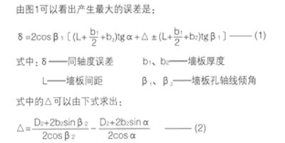
The positioning method of the coaxial accuracy of the traditional basic parts mostly adopts the mandrel positioning method. Theoretically speaking, this method can be used to design the datum, the assembly datum, and the positioning datum. The datum can improve assembly accuracy. However, due to the presence of shape, position and size errors in the positioning holes of the wall plate, the positioning part of the mandrel also gives a given tolerance value. Therefore, when two wall plates are positioned using the mandrel, the existence of the gap will cause the mandrel to rotate flexibly. Concentricity error. Obviously, with the widening of the distance between the two wallboards, the coaxiality error value and the wallboard spacing are proportional to the size of the fit gap. The error of coaxiality caused by the presence of gaps in large-span printing machine wallboard can not be ignored. Although the relative positions of the rollers, shafts, and rollers can be determined from the common axis after the assembly of the rollers, shafts, and rollers, it seems that the impact is not significant. However, many transmission, control, and automatic control parts are in poor working conditions. More important is poor accuracy.
To establish the relationship between gaps, wall spacing and concentricity errors, first propose the following constraints:
1. The lower plane of the wall plate is the support reference, and is also the guiding reference during processing. Therefore, it can be considered that all co-located holes on the two wall plates are the same as the supporting reference height dimension. When assembling, the horizontal position of the two wall plates is determined by the positioning core. Axis positioning determination;
2. It can be imagined from an intuitive point of view that the position that produces the maximum concentricity error is: the two ends of one hole are in contact with the positioning mandrel diagonally (see Figure 2), and the other hole is positioned inside the mandrel (see Figure 2). Figure 1) Theoretically speaking, the rotation of the mandrel should also be flexible;


3. The wall plate is assembled on the curved plate elevation (horizontal boring machine processing) or on the work table in the vertical machining (or it can be divided and processed), so the axis of the two wall plate holes is considered to be in the same direction, but the wall plate is The large planes have different angles, which reflects the consistent accuracy of the pull (beam) parts;
4. Generally speaking, the two wallboards have the same hole diameter. In order to make the deduced relationship have universal significance, the two corresponding holes are not equal.